
Implant Machining Surface Finishing: The Complete Guide to Biocompatible Surfaces
At Implantmfg, we see surface finish not as a secondary spec but as a core performance attribute of every implant we machine. Whether it’s a titanium hip stem, a cobalt-chrome knee component, or a PEEK spinal cage, the surface we deliver directly influences how the implant interacts with the body, how long it lasts, and whether it meets regulatory standards. In this guide, I’ll walk through everything you need to know about implant machining surface finishing — from roughness metrics to material-specific challenges, from machining processes to emerging innovations.
---
Why Surface Finish Is Critical for Implant Performance
Surface finish is the interface between implant and biology. It determines:
- Biocompatibility: Rough or contaminated surfaces can trigger inflammation or fibrous encapsulation, delaying healing.
- Wear resistance: Articulating surfaces (hip ball, knee condyle) must be smooth enough to minimize particle debris, which can cause osteolysis.
- Bone integration: Bone-facing surfaces need controlled roughness to encourage osteoblast attachment and ingrowth.
- Regulatory approval: FDA and notified bodies require documented evidence that your surface finish meets design intent and is reproducible.
I’ve seen projects where a seemingly minor increase in Ra from 0.1 µm to 0.15 µm on a femoral head led to accelerated wear in simulator testing. Conversely, a polished bone-contact surface that was too smooth failed to achieve primary stability in animal studies. Every micron matters.
Patient safety depends on a consistent, validated surface finish. That’s why at Implantmfg we treat surface finish control as seriously as dimensional tolerances.
---
Key Surface Roughness Metrics and Standards
When we talk surface finish, we use standardized parameters. The most common are:
- Ra (Arithmetic Average Roughness): The average deviation from the mean line. Most widely specified.
- Rz (Average Maximum Height): Average of the five highest peaks and five lowest valleys over a sampling length. More sensitive to outliers.
- Rq (Root Mean Square Roughness): Statistically more sensitive to peaks and valleys than Ra.
- Rmax (Maximum Roughness Depth): The largest single peak-to-valley distance.
For medical implants, the governing standards are ISO 25178 (areal surface texture) and ASTM F86 (surface finish for metallic surgical implants). ASTM F86 recommends that for articulating surfaces, Ra should be ≤ 0.05 µm; for bone-contact surfaces, Ra typically falls in the 1–3 µm range, sometimes with a defined texture.
What is the recommended surface roughness for implants?
- Articulating surfaces (hip, knee, shoulder): Ra < 0.1 µm, often 0.02–0.05 µm
- Bone-facing surfaces (cementless): Ra 1–3 µm, sometimes with porous or roughened texture
- Dental abutments: Ra < 0.2 µm for soft-tissue contact; micro-roughness (Ra ~1–2 µm) on bone-facing threads
- Spinal implants: Ra 0.4–1.0 µm for PEEK; Ra 1–3 µm for titanium cages
These metrics guide our machining and finishing decisions: we choose tools, feeds, and sequences to hit the target profile without introducing subsurface damage.
---
---
Implant Materials and Their Finishing Needs
Different materials respond differently to machining and finishing. Here’s how we handle the most common ones:
Titanium (Ti-6Al-4V, Grade 5)
- Challenges: Gummy, low thermal conductivity, work hardening. Prone to smearing and built-up edge.
- Finishing approach: Sharp tools, high-pressure coolant, moderate speeds. Best finished with chemical or electrochemical methods post-machining (electropolishing, passivation) to remove smeared layers and improve corrosion resistance.
- Additive manufacturing (AM): Parts from powder bed fusion have rough as-built surfaces (Ra 10–20 µm) that require aggressive smoothing (shot blasting, abrasive flow machining, then electropolishing).
Cobalt-Chrome (CoCr)
- Challenges: Hard, abrasive, high cutting forces. Tool wear is significant.
- Finishing approach: Use carbide or ceramic tools, low speeds, high feed. Mechanical polishing is typical for articulating surfaces; electropolishing can reduce microcracks.
- Cast vs. wrought: Cast CoCr has a coarser microstructure, making mirror finish harder. Wrought material finishes more consistently.
316L Stainless Steel
- Challenges: Reasonably machinable, but prone to work hardening and burr formation.
- Finishing approach: Good using conventional polishing; passivation (nitric acid) is required to restore the chromium oxide layer after machining.
PEEK (Polyetheretherketone)
- Challenges: Soft, burns easily, stringy chips. Not suitable for mechanical polishing to high gloss.
- Finishing approach: Use sharp tools, high clearance angles, and coolant. Surface finish is typically left as-machined (Ra 0.4–1.0 µm) or can be plasma-treated for improved wettability.
Bioceramics (Alumina, Zirconia)
- Challenges: Extremely hard, brittle. Machining is limited to grinding/lapping.
- Finishing approach: Diamond abrasives, ELID (electrolytic in-process dressing) grinding. Surface finish can reach Ra < 0.02 µm.
---
Machining Processes for Implant Surface Finish
What is the machining process for surface finish?
A typical sequence for an implant component follows four stages:
- Roughing: Remove bulk material quickly, leaving ~0.5–1 mm stock. Use larger tools, high depths of cut. Priority is material removal rate, not finish.
- Semi-finishing: Reduce stock to ~0.1–0.3 mm. Smaller stepovers, finer feeds. Correct for deflection.
- Finishing: Final cut to achieve target dimensions and surface quality. For Ra < 0.2 µm, use wiper inserts, small nose radii, and reduced stepover (0.1–0.2 mm).
- Superfinishing (if needed): Mechanical polishing, abrasive flow, or electropolishing to achieve Ra < 0.05 µm.
Tool selection and parameters
- Cutting speeds: For titanium, 40–60 m/min (finishing). For CoCr, 20–30 m/min.
- Feed rates: 0.05–0.15 mm/rev for finishing on turning; 0.02–0.06 mm/tooth for milling.
- Coolant: High-pressure through-tool coolant (70–100 bar) for titanium to reduce heat and prevent smearing.
- Tool material: Carbide with PVD coatings (TiAlN, AlCrN) for Ti and CoCr; PCD for abrasive materials.
Subsurface damage is a major risk in implant machining. Excessive heat or aggressive feed can induce microcracks, residual tensile stress, or phase transformations (especially in CoCr and titanium). We mitigate this through conservative cutting parameters, sharp tools, and controlled coolant application.
---
Surface Finishing Techniques for Implants
Beyond machining, we apply secondary finishing operations tailored to the implant function.
| Technique | Best for | Limitations |
|-----------|----------|-------------|
| Mechanical polishing | Articulating surfaces (hip, knee) | Labor-intensive; inconsistent if manual; can embed abrasive particles |
| Electropolishing | Titanium, stainless steel, CoCr | Removes smeared layer; excellent for complex geometries; cannot create directional texture |
| Passivation | Stainless steel, titanium | Required by ASTM F86; removes free iron, restores oxide film |
| Shot blasting / grit blasting | Bone-contact surfaces (cementless) | Creates uniform texture; risk of media contamination if not cleaned |
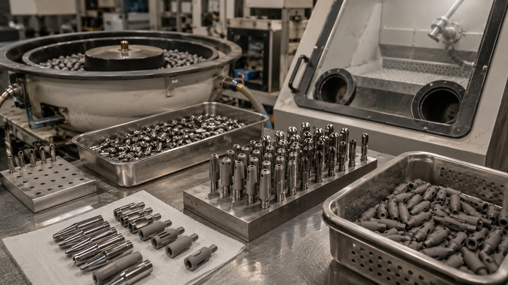
| Mass finishing (vibratory, centrifugal) | Small parts, deburring, bulk processing | Limited control over specific areas; geometry-dependent |
| Laser polishing | Emerging for AM parts; non-contact | High capital cost; parameter development needed per material |
| Plasma electrolytic oxidation (PEO) | Titanium only; creates porous, wear-resistant, bioactive oxide | Adds thickness; must account for dimensional change |
For additive manufacturing implants, post-processing is critical: support removal, hot isostatic pressing (HIP) to close porosity, then surface smoothing (abrasive flow, electropolishing, or laser polishing). At Implantmfg, we work with partners who specialize in AM finishing, ensuring that the final part meets both geometry and surface requirements.
---
How Surface Finish Affects Biocompatibility
Surface texture is a language that cells read. Osteoblasts (bone-forming cells) respond to roughness in a dose-dependent way:
- Smooth surfaces (Ra < 0.1 µm): Promote fibroblast attachment (soft tissue). Used for trans-mucosal dental abutments.
- Moderate roughness (Ra 1–2 µm): Stimulates osteoblast proliferation and differentiation. Ideal for cementless bone-contact surfaces.
- Very rough surfaces (Ra > 3 µm): Can trap debris, harbor bacteria, and cause fatigue. Generally avoided unless porous coatings are applied.
Coating adhesion (hydroxyapatite, antibacterial silver, etc.) also depends on surface energy and roughness. A consistent micro-roughness increases mechanical interlocking.
Warning: Too-smooth bone-contact surfaces fail because cells cannot grip. We’ve had customers request a mirror finish on a femoral stem — and we advised them against it based on clinical evidence.
---
Controlling Wear and Tribology via Surface Finish
In articulating joints, friction and wear are controlled by:
- Surface roughness: Smoother surfaces (Ra < 0.05 µm) reduce abrasive wear against polyethylene or ceramic counterfaces.
- Lubrication film thickness: Roughness peaks can break through the synovial film, causing direct contact and wear.
- Cross-hatch pattern: On metal femoral heads, a defined lay pattern (often 45° to motion) retains lubricant and reduces friction.
What is the recommended surface roughness for articulating implants?
For metal-on-polyethylene, Ra typically ≤ 0.05 µm. For ceramic-on-ceramic, even smoother (< 0.02 µm). We achieve these levels through a combination of precision turning and polishing.
Wear mechanisms linked to surface finish:
- Abrasive wear: Caused by hard particles (wear debris or surface asperities). Smoother finish reduces.
- Adhesive wear: Occurs when surfaces cold-weld; smooth, hard surfaces (e.g., DLC coatings) help.
- Fatigue wear: Cracks initiated at surface defects (scratches, pits). Good finish reduces stress concentration.
How to improve surface finish in machining?
Here are five practical tips we use daily:
- Use fine feed rates (≤ 0.08 mm/rev for turning; ≤ 0.05 mm/tooth for milling).
- Switch to wiper inserts — they produce a flatter surface with the same feed.
- Optimize toolpath: constant engagement, avoid sharp corners, use trochoidal milling for difficult materials.
- Employ a steady rest for long slender turning to eliminate vibration chatter.
- Add polishing passes (0.1 mm depth, high speed, light cut) after finishing.
---
Matching Surface Finish to Implant Function
Every implant zone has a purpose-driven roughness requirement:
- Articulating surfaces (hip ball, knee femoral condyle, shoulder humeral head): Ra < 0.05 µm, mirror-like, often with directional pattern (cross-hatch) to promote lubrication.
- Bone-facing surfaces (cemented femoral stem, cementless acetabular cup): Ra 1–3 µm for cementless; Ra 0.2–0.5 µm for cemented to improve cement adhesion. Often textured (grit-blasted, porous coated).
- Dental implants: Micro-roughness on bone-contact threads (Ra 1–2 µm), smooth machined neck (Ra < 0.2 µm) to inhibit plaque.
- Spinal implants: PEEK cages typically Ra 0.4–1.0 µm as-machined; titanium cages often roughened (Ra 1–3 µm) for bony ongrowth.
- Trauma plates and screws: Balance between strength (smooth surface reduces stress risers) and corrosion resistance (passivation essential). Ra 0.4–0.8 µm is common.
---
Regulatory Requirements and Documentation
Regulatory bodies expect demonstrable control over surface finish.
- FDA QSR (21 CFR 820): Requires process validation for finishing operations that affect safety or performance. You must prove that your process consistently produces the specified surface.
- ISO 13485: Demands documented procedures, calibration of surface profilometers, and traceability.
- ISO 10993 (Biocompatibility): Surface finish impacts leachables, roughness, and cleaning validation. A rough surface can trap contaminants; you must show that cleaning is effective.
Common audit findings:
- Inconsistent surface roughness between batches (lack of SPC).
- Missing or incomplete process validation for polishing/electropolishing.
- Contamination from finishing media (e.g., embedded alumina from blast media).
- Inadequate cleaning validation for complex internal geometries.
At Implantmfg, we support customers with inspection reports (including surface roughness measurement data), material traceability, and batch records. We treat documentation as part of the product.
---
Trends and Innovations in Implant Surface Finishing
Additive Manufacturing
AM parts have inherent roughness (Ra 10–20 µm) and require post-processing. Hybrid solutions (machining + electropolishing) are common. We see growing use of chemical mechanical polishing for internal channels.
Smart Surfaces
Laser texturing can create patterns that repel bacteria or promote osseointegration. Drug-eluting coatings (antibiotics, growth factors) benefit from controlled micro-roughness for consistent elution.
Digital Twin and Simulation
While simulation can predict machining forces and tool wear, surface roughness is highly dependent on material microstructure, tool condition, and coolant effectiveness. Empirical validation is still essential.
Sustainability
Reducing polishing waste (abrasive slurries, chemical baths) is a priority. Dry electrochemical polishing and closed-loop coolant systems are emerging.
In-Process Metrology
Closed-loop machining — where an on-machine probe or laser measures surface roughness mid-process and adjusts parameters — is becoming feasible for high-value implants. We’re piloting this for femoral heads to reduce scrap.
---
FAQ
What is the recommended surface roughness for implants?
It depends on location:
- Articulating surfaces: Ra < 0.1 µm (often 0.02–0.05 µm)
- Bone-contact (cementless): Ra 1–3 µm
- Bone-contact (cemented): Ra 0.2–0.5 µm
- Dental (trans-mucosal): Ra < 0.2 µm
What is the machining process for surface finish?
Roughing → semi-finishing → finishing → superfinishing. Each stage uses progressively finer feeds, smaller depths, and specialized tools (wiper inserts, polished inserts). After machining, secondary processes like electropolishing or finishing may be applied.
What is the standard surface finish for machined parts?
General machining often uses Ra 3.2 µm (125 µinch). Implant-grade articulating surfaces require Ra 0.1 µm or better — an order of magnitude smoother. Do not assume a standard “machine finish” meets implant requirements.
How to improve surface finish in machining?
Top 5 practical tips:
- Reduce feed rate (≤ 0.05 mm/rev for finishing)
- Use wiper inserts or polished inserts
- Optimize toolpath to avoid sudden engagement changes
- Apply steady rest or tailstock support to eliminate chatter
- After roughing, add a finishing pass with 0.1 mm depth at high speed and fine feed
---
Partner with Implantmfg for Precision Implant Machining
Surface finish is not an afterthought — it’s engineered from the first cut. At Implantmfg, we bring years of experience machining titanium, PEEK, cobalt chrome, and stainless steel for orthopedic, spinal, dental, and trauma implants. We work from your drawings, support prototype through production, and deliver components with documented surface quality.
Whether you need a single prototype or a repeat production run, our team can help you select the right machining and finishing strategy for your implant.
Contact Implantmfg today to discuss your custom implant machining project. Send us your design, and we’ll provide DFM feedback and a detailed proposal.